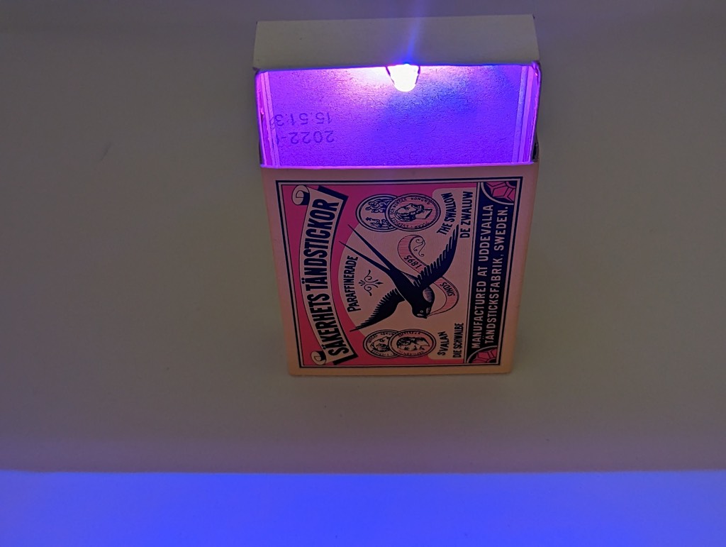
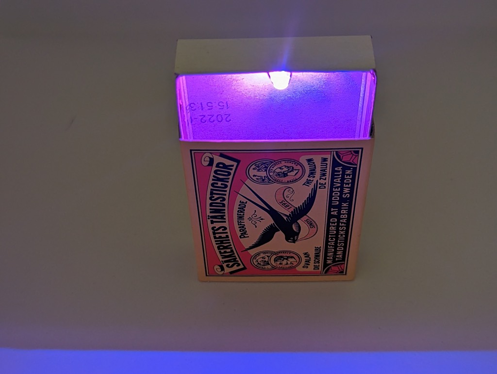
Make a surprise RGB-LED matchbox. When you open the box the RGB-LED will switch itself on. When closed it’s turned off by the self made switch. All in all this is not a soldering challenge, just a few points to solder 😉 But it looks nice in my cupboard.
and of course a soldering iron with some solder, and other tools….
Circuit
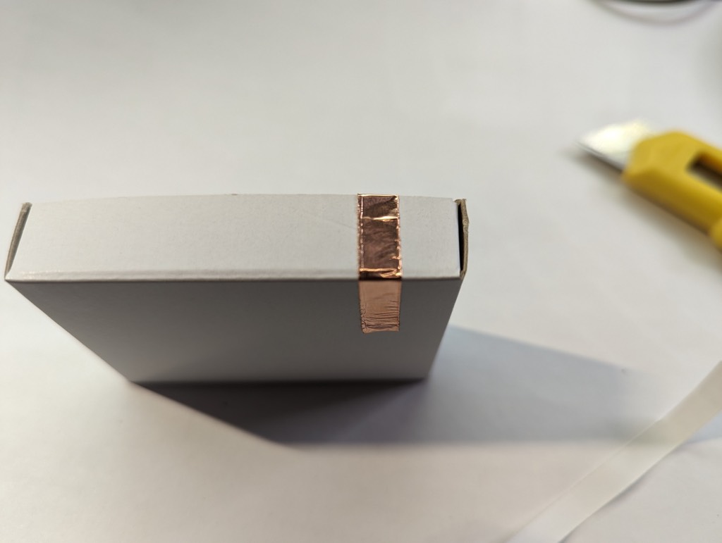
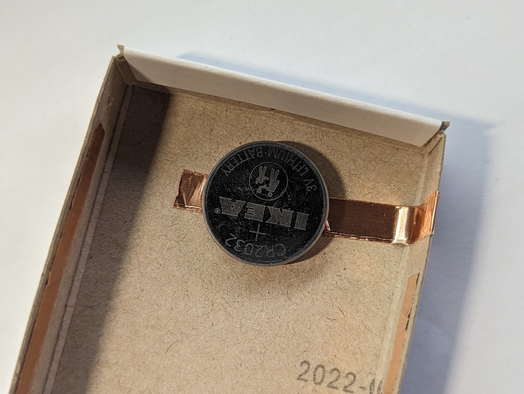
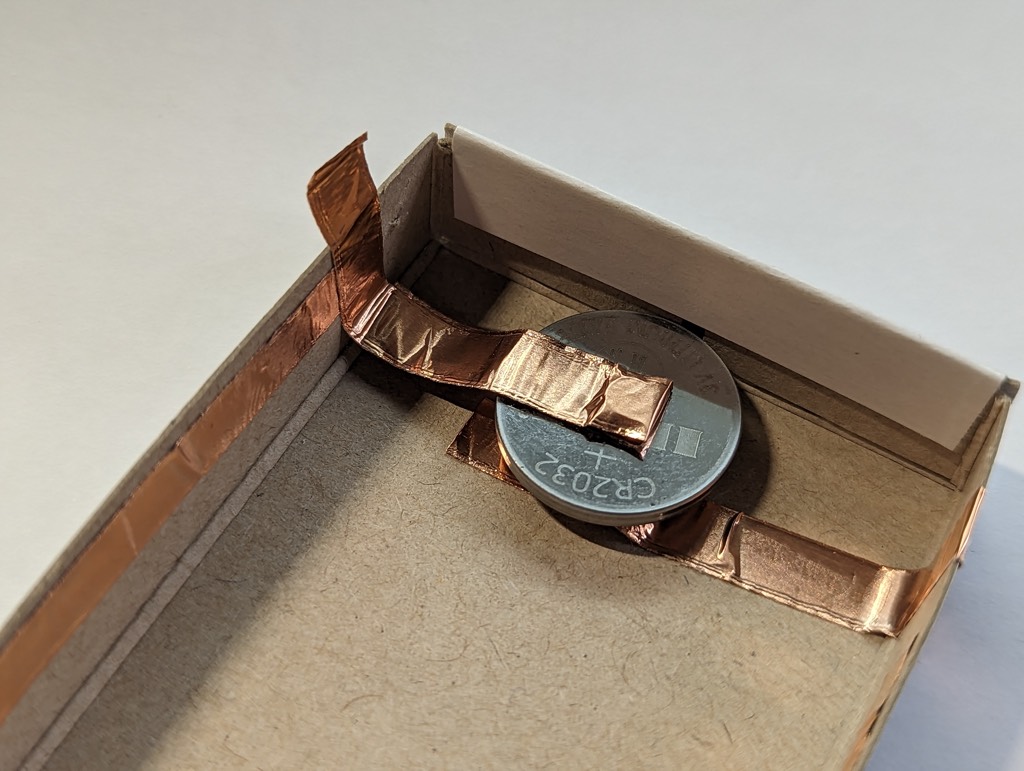
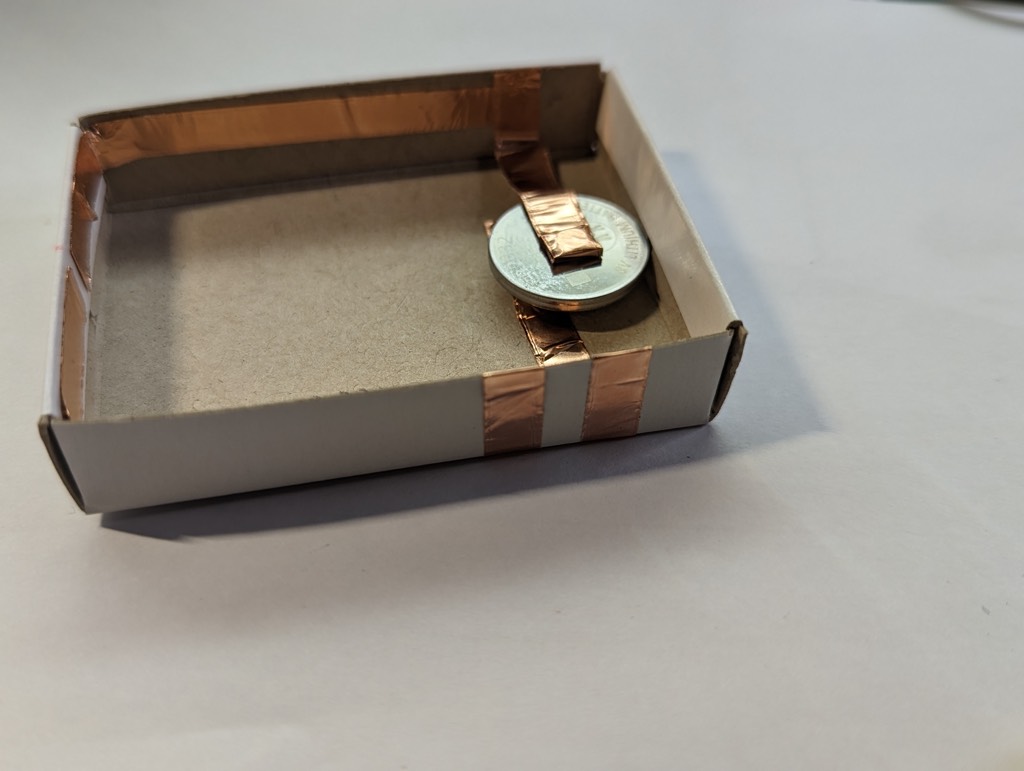
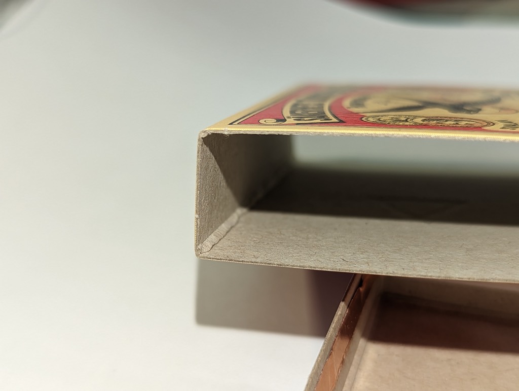
The copper tape conducts electricity from the battery to the LED. The battery has a positive and a negative side. Often the positive side is marked with a ‘+’ sign. The LED also has a positive leg (long) and negative leg (short). I use some copper tape on the inside of the outer box and the outside of the inner box to act as a switch. The battery is locked in between two neodymium magnets and some copper tape, so you can replace the battery when needed.
Step by step instructions
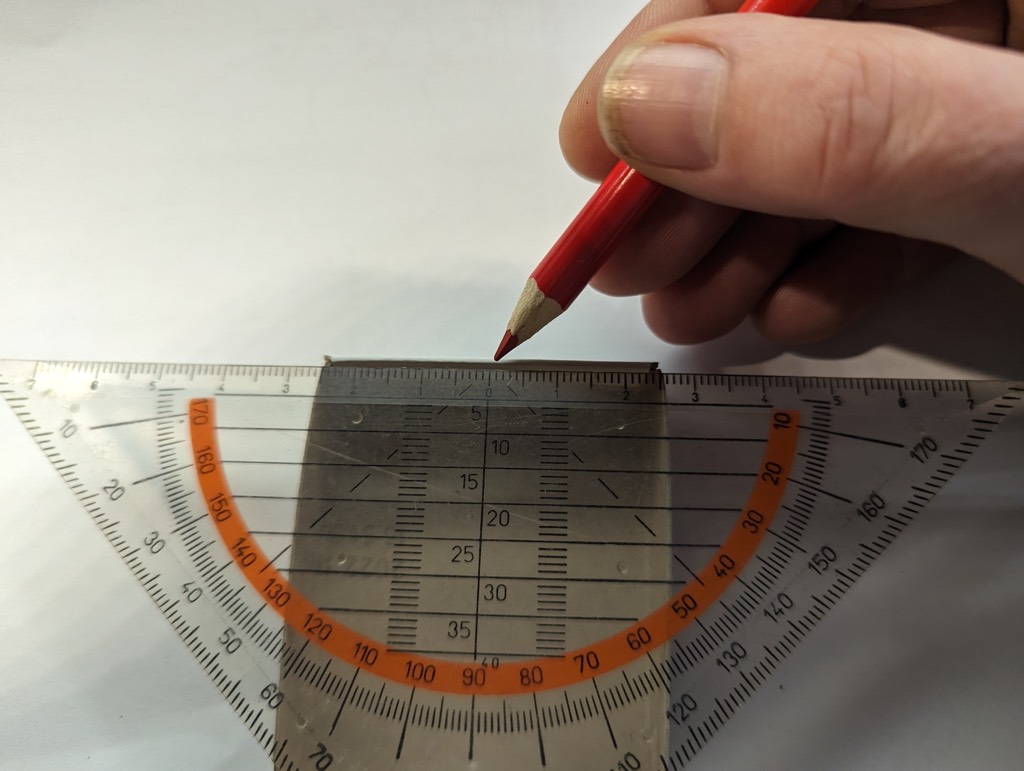
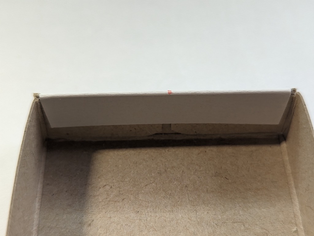
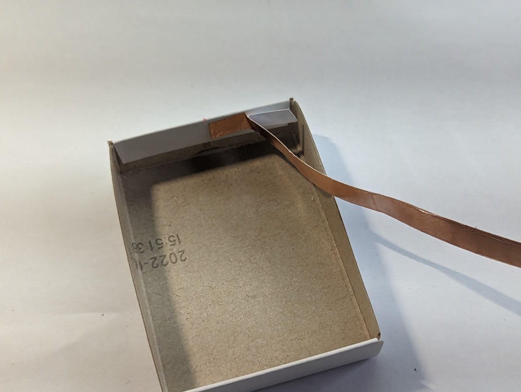
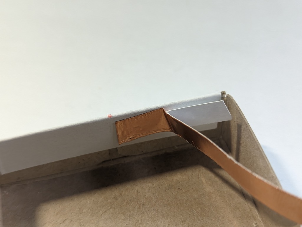
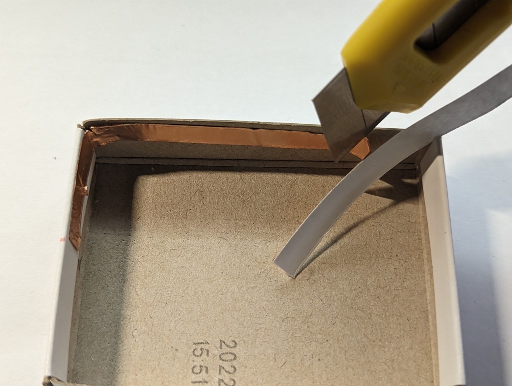
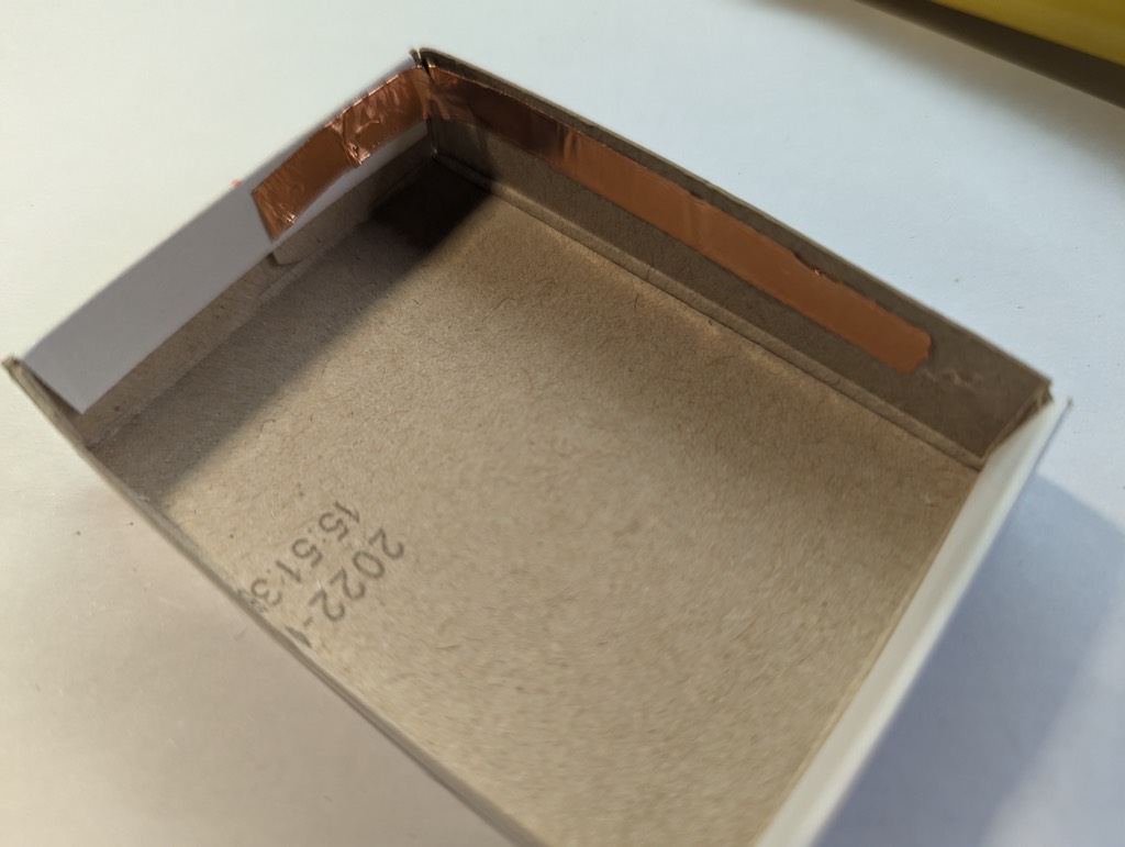
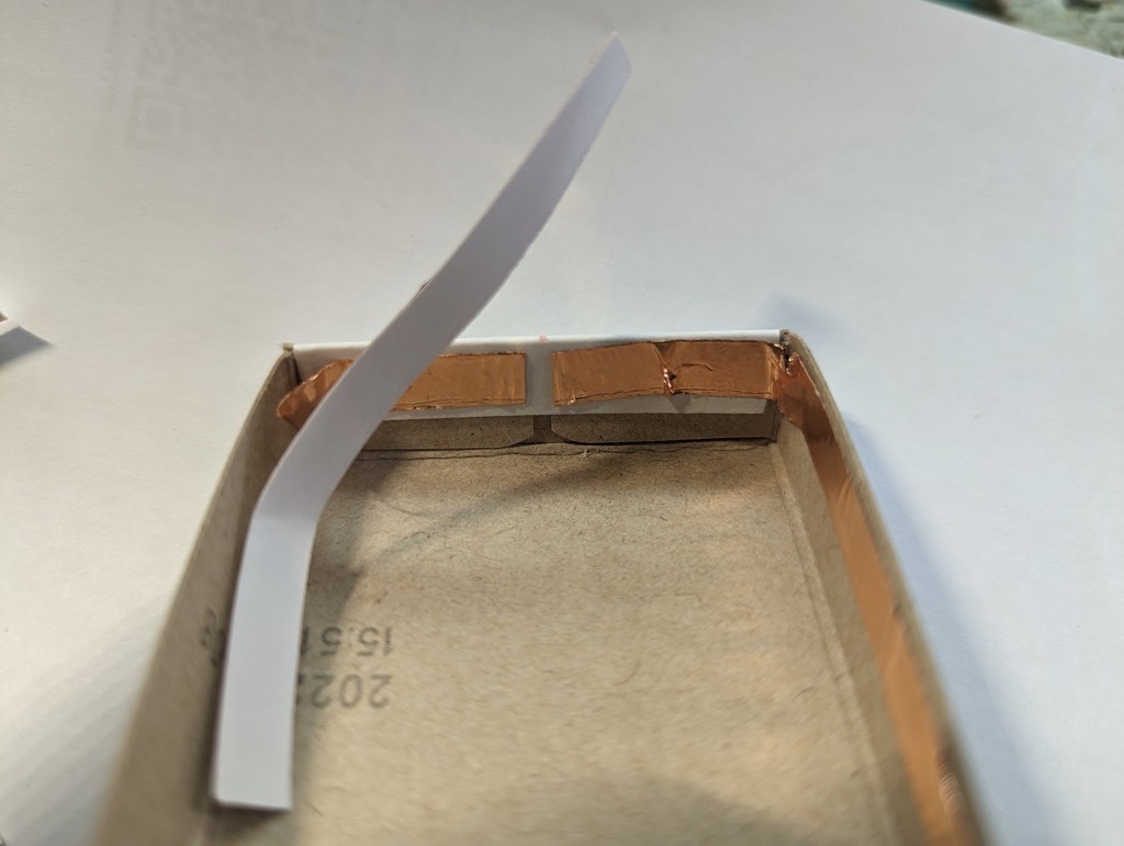
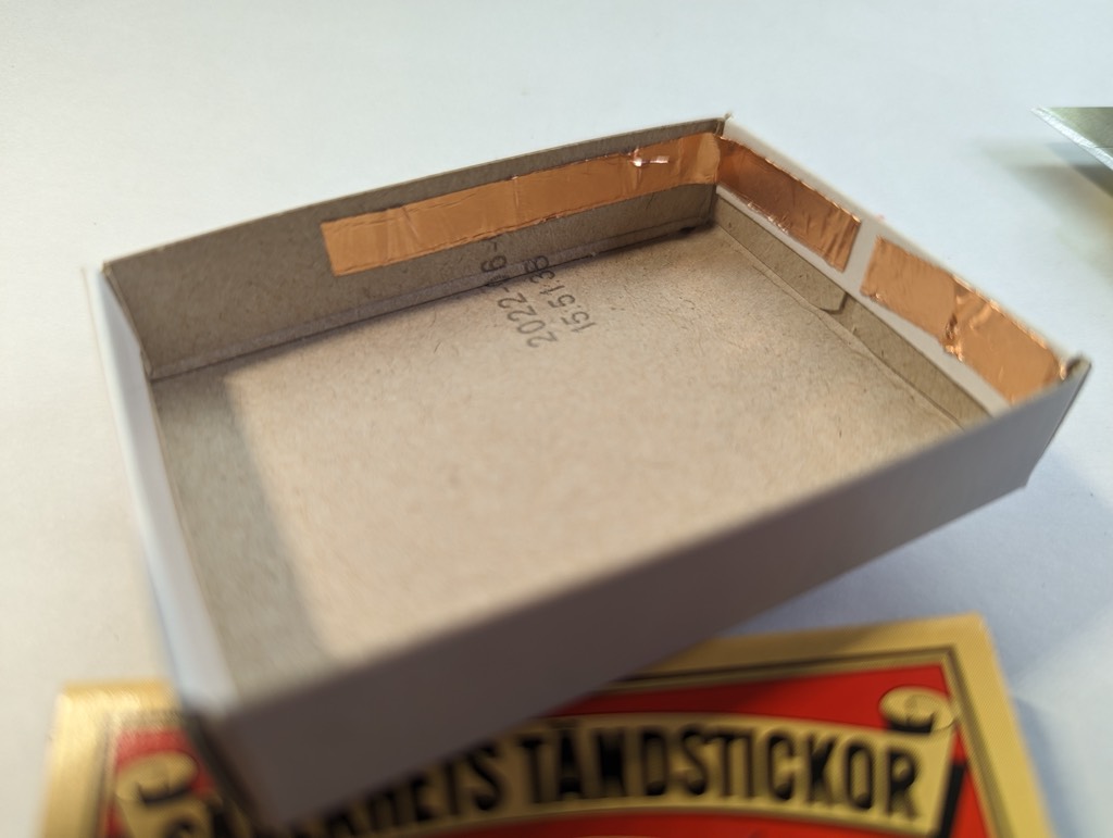
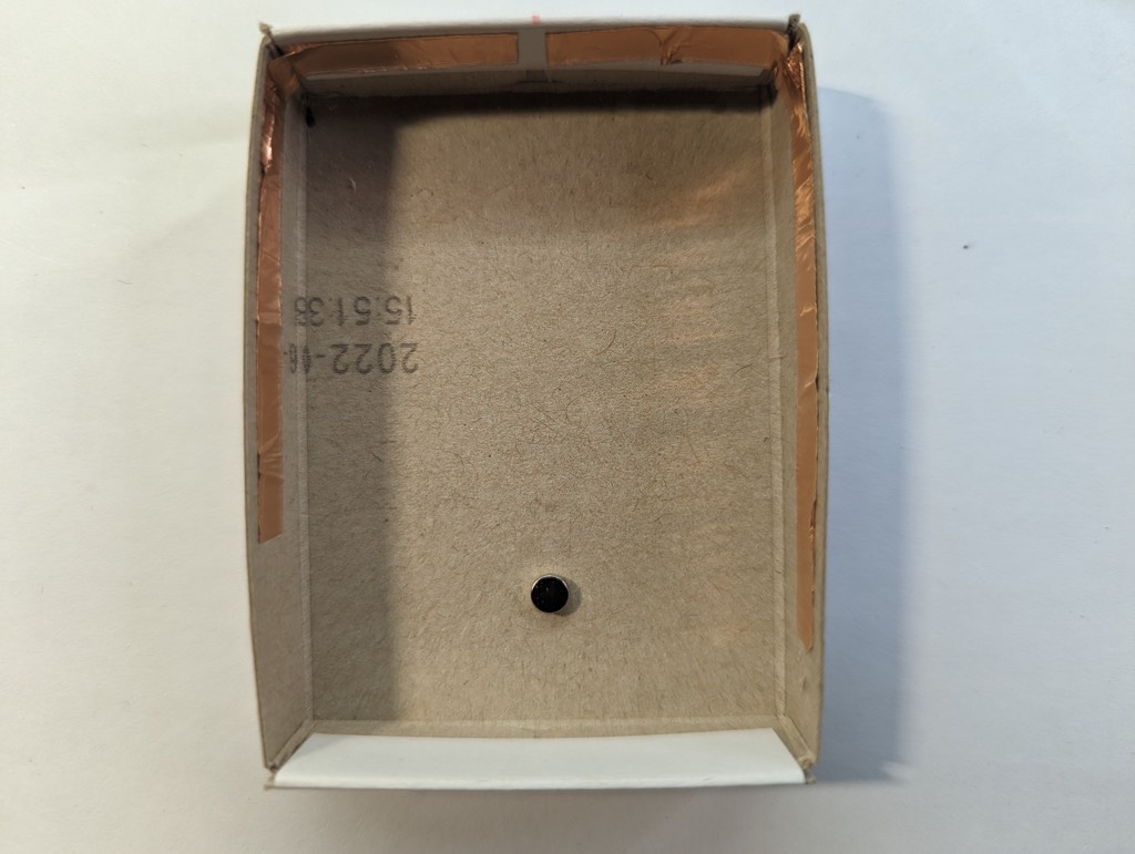
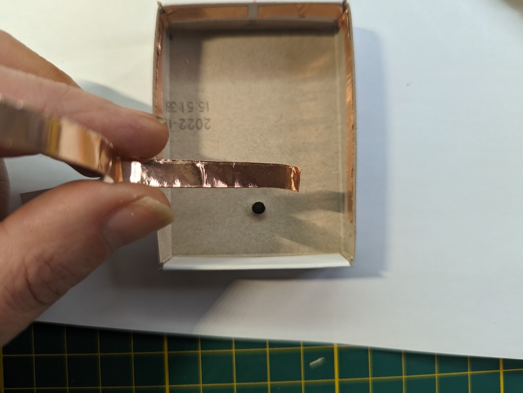
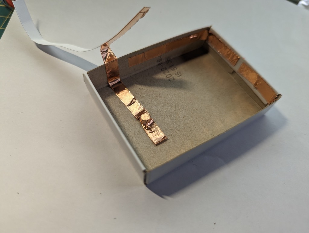
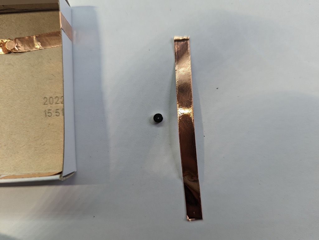
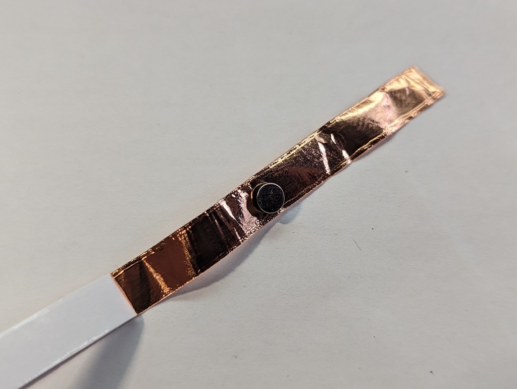
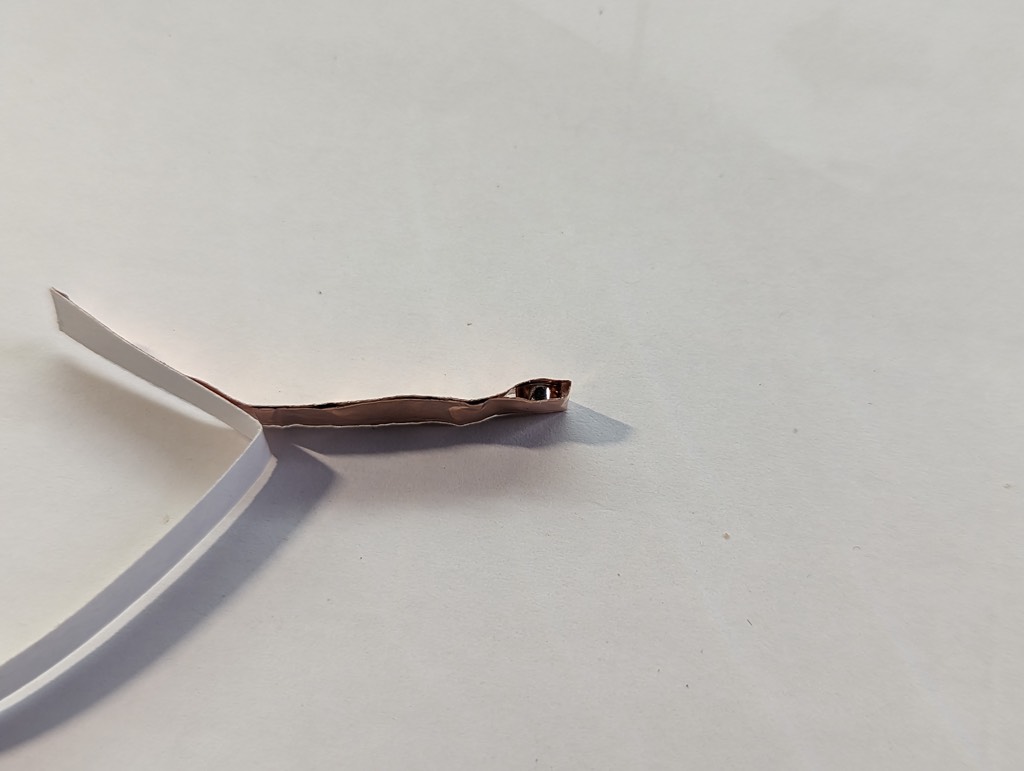
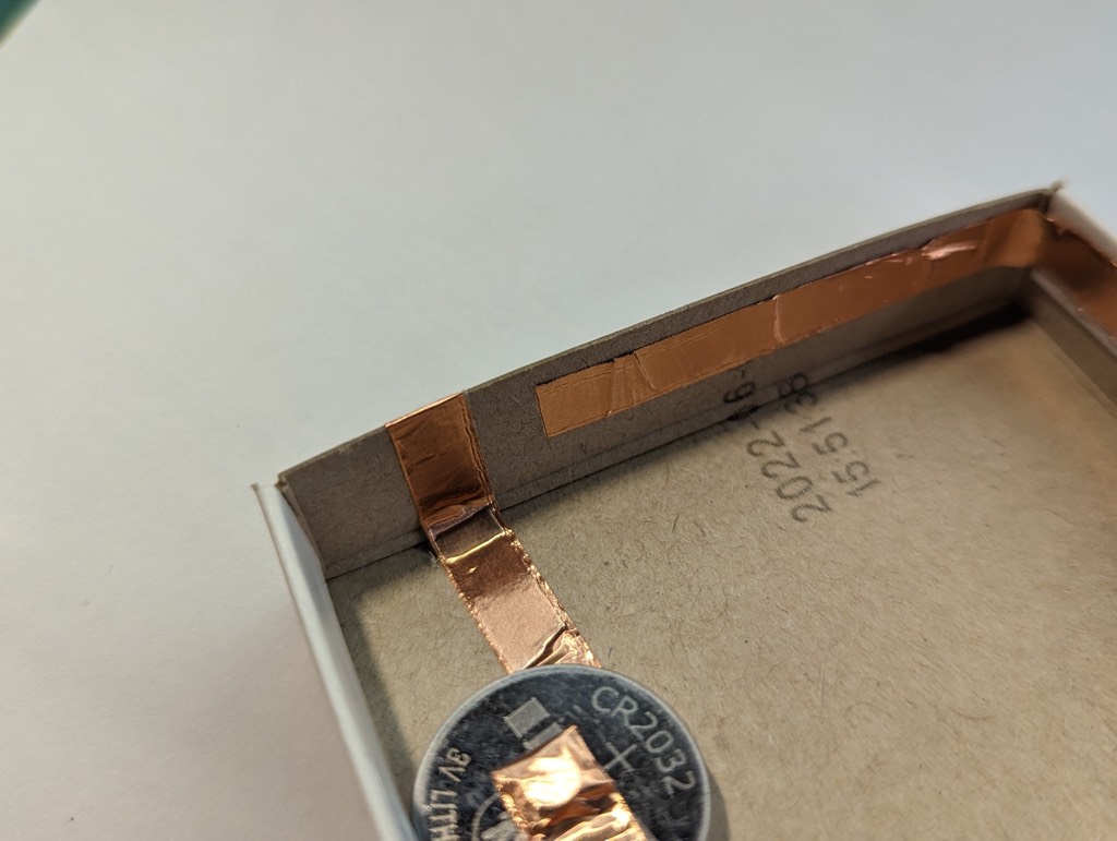
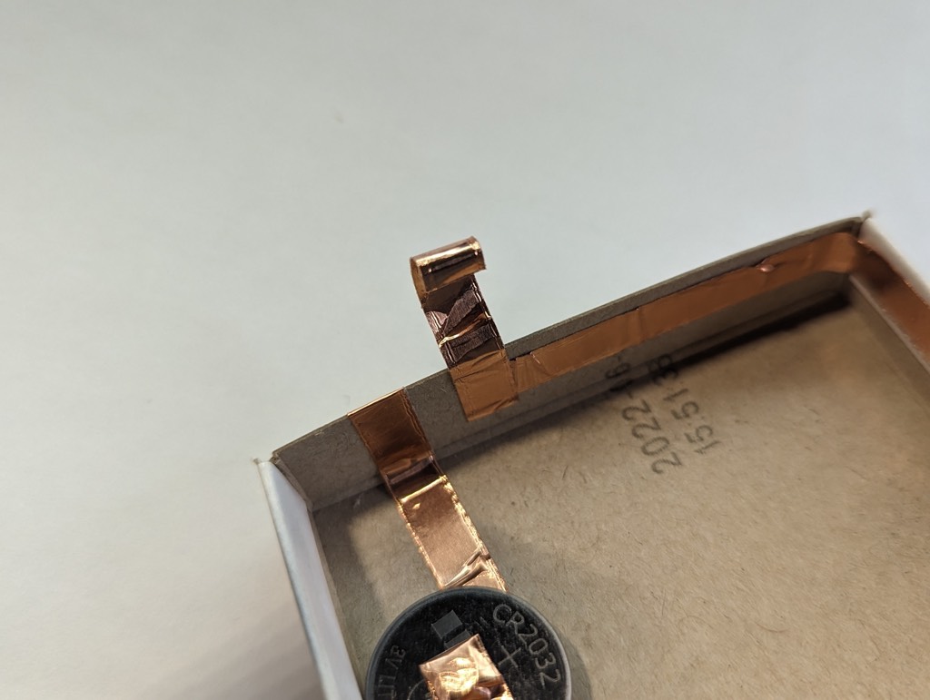
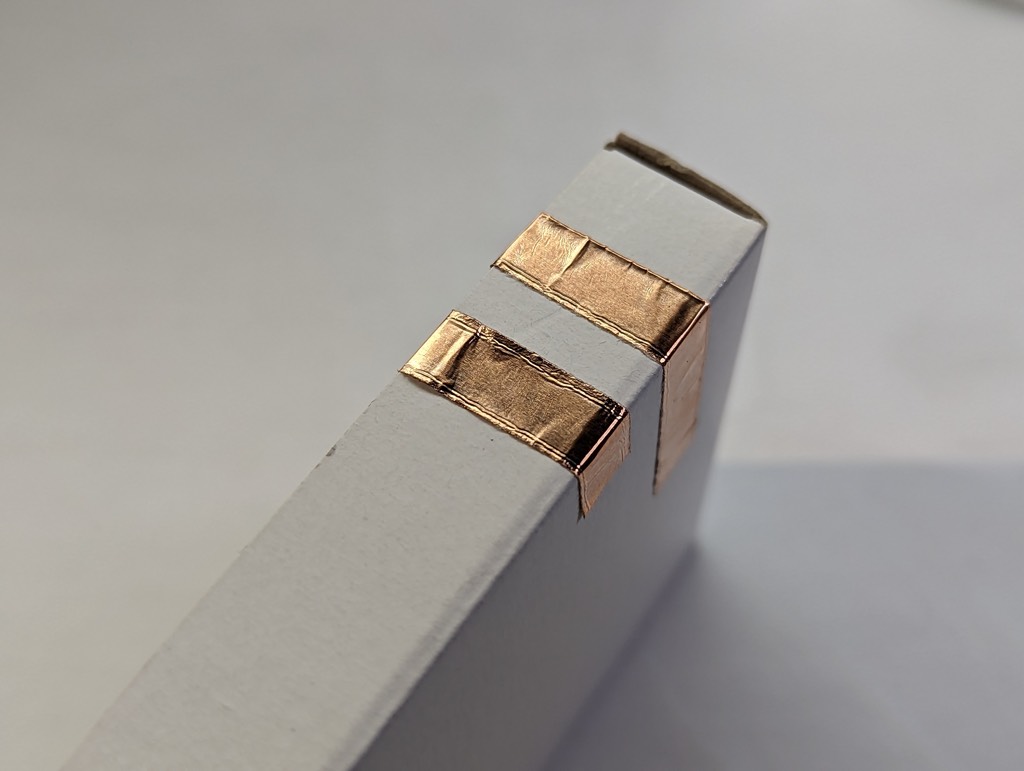
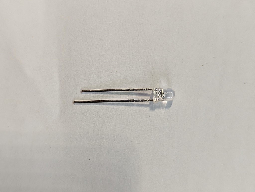
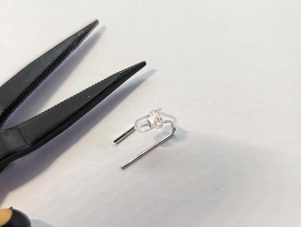
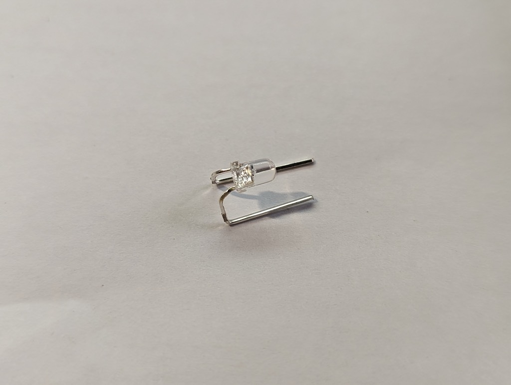
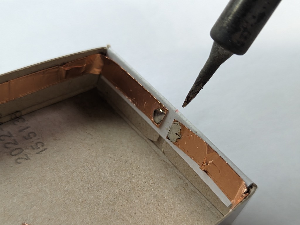
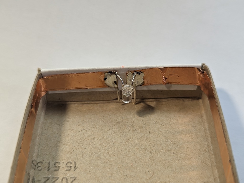
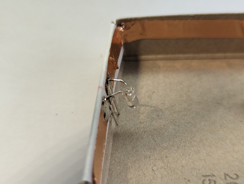
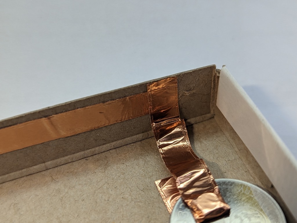
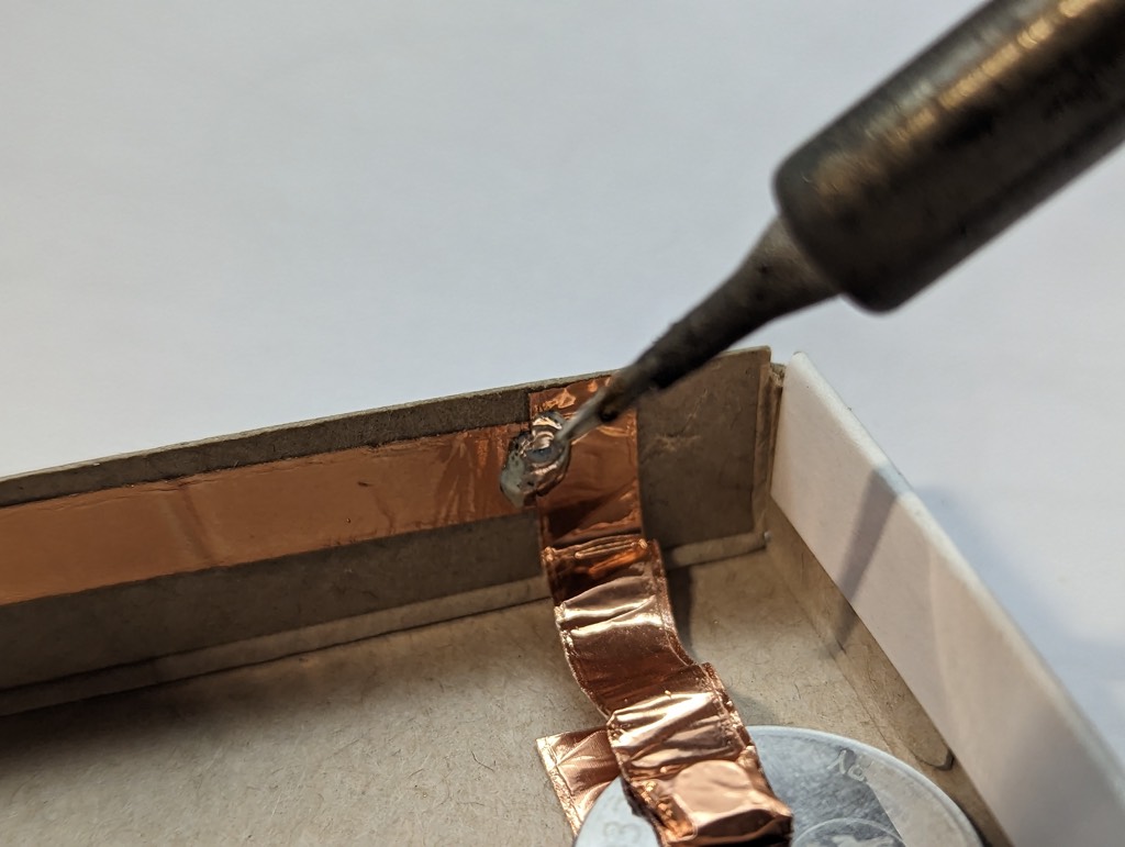
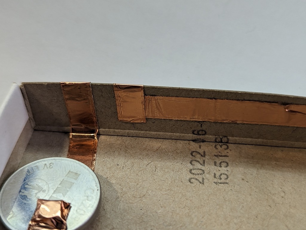
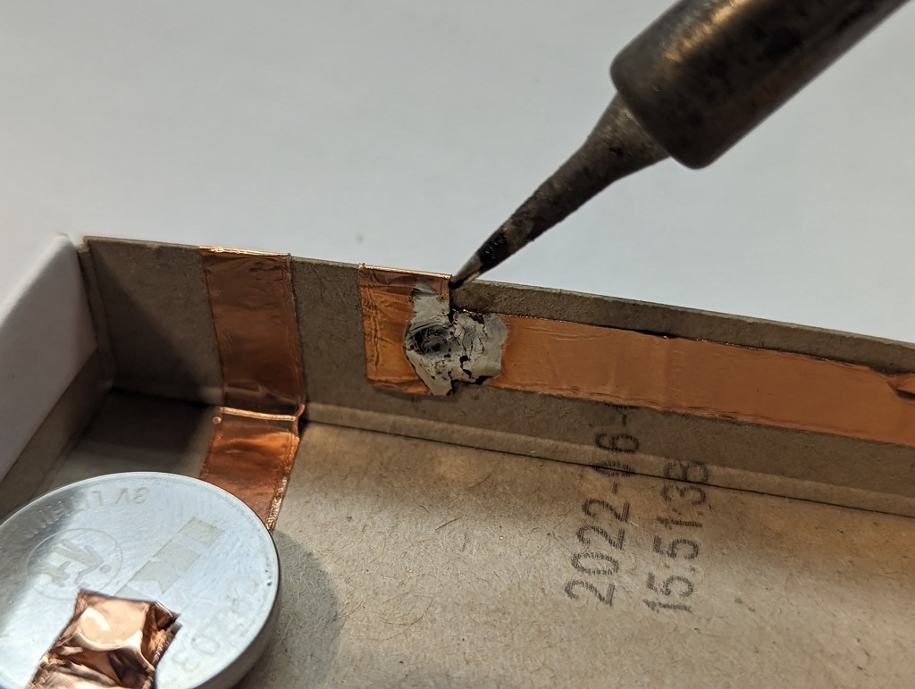
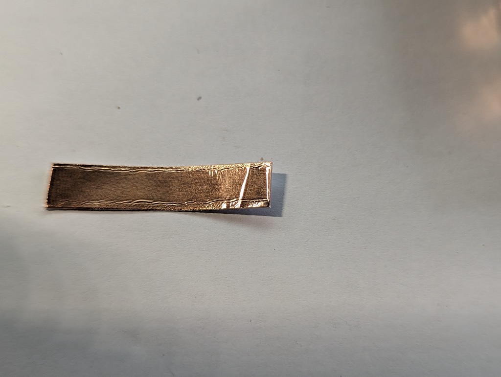
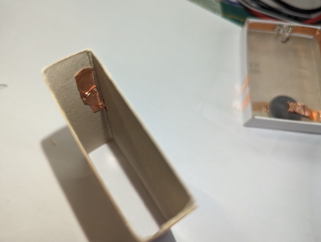
Basic soldering project: Matchbox LED surpriseEmpty the boxMeasure and mark the middleThe red dot is the middleStart just right of the middle with copper tape, we’ll leave intentionally a gap in the middleGo around the corner and stop & cut the tapeResult: it should be like this nowFor the opposite site, start left of the middle, mind the gapAround the corner, and stop earlier than the first timePlace a neodymium magnet. The battery will be on top of it later, so guess where the center of the CR2032 would be. Use copper tape to fixate the magnet, use some overlapResult. Continue with the copper tape over the edge, around the bottomGet a piece of copper tape, it’ll become the second copper stripPeal some of the back of the copper tape, not all, place the second neodymium magnet in the middleWrap the copper tape on itself, fixating the magnet.In the meantime place the battery in the box, positive side up.Place the second copper strip on the battery and peal of the rest of the back on stick it to the other copper lane inside the box.Cut off the excess tape. The result is a changeable battery compartment.The other copper lane…..Get some copper tape, connect it to the inside copper lane, go around the edge to the bottom Like thisAnd thisNow for the RGB LED. The long leg is positive, short negative. Bend the legs two times, keep the long leg to the right.ResultPrepare the copper for the LED, put some solder on the endSolder the LED one leg at the time. The right side should be the long positive legResultThe joints of the copper tape should connect properly. Although the tape is sold as conductive on both sides, I find it better to solder the joints so I’m shure that there is a good solid connection.Just a drop of tinAlso on the other side…Just a drip…On the inside of the outer box…place some copper tape. It’s the switch which makes the circuit and let’s the current pass.The place is depending on the two copper strips on the outside of the inner box. When it’s pushed open it should connect those two, but not when closed.Here it is….